But if you have mastered the basics of working with Arduinos, I hope this, the downloadable source code, and referenced pages will give you everything you need to complete it. At some level. (That comment will be explained further!)
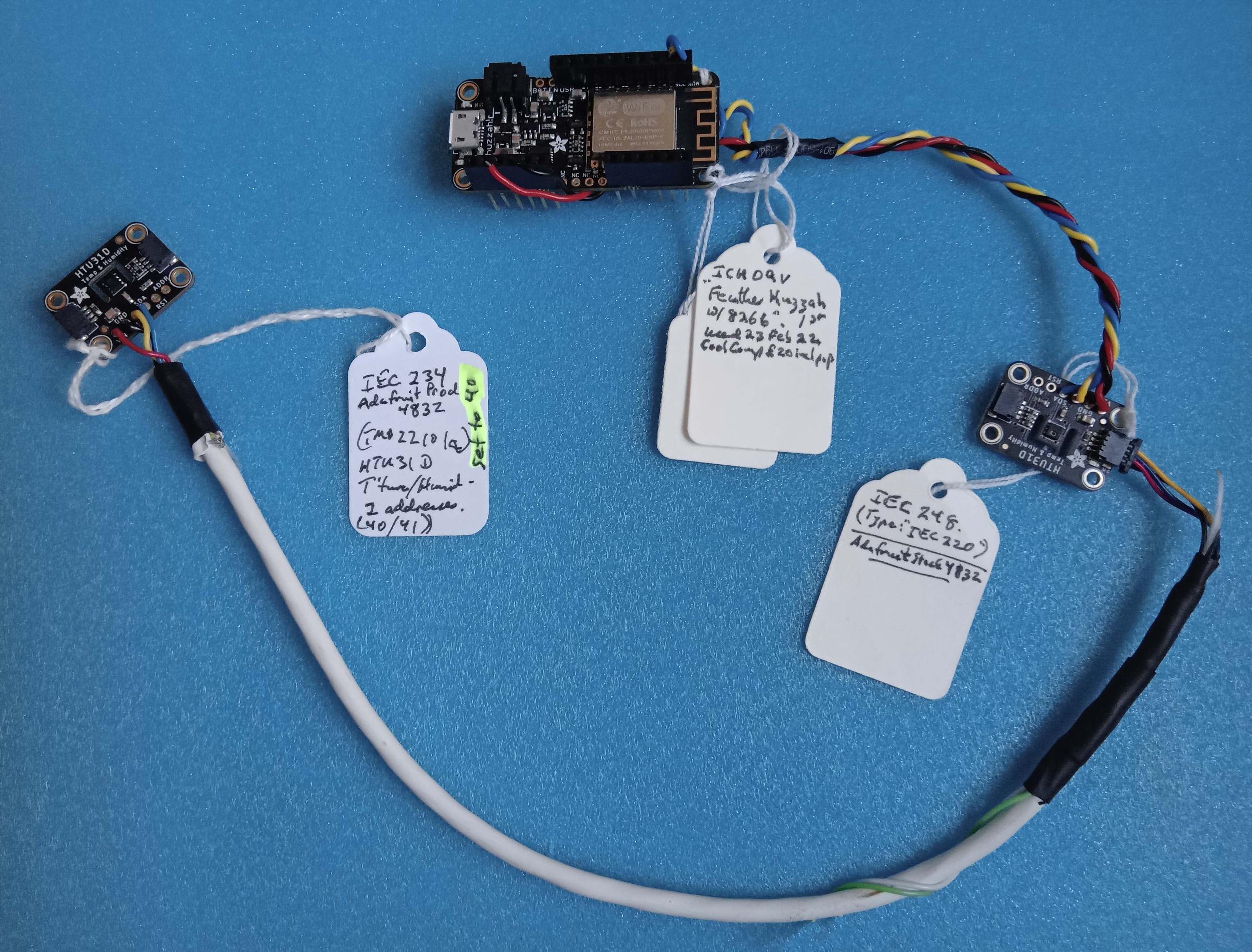
Above: The whole hardware for the project. Simples!
---
I'm told... though I never learn to listen to the wisdom... that it is best if you know where you are going before you start moving.
It's just that it's more fun to be DOING something, not PLANNING something.
So, time and again, I do a wonderful job of some aspect of a project only to find I've spent time on a dead end, and have to retrace my steps.
More importantly, if you are careful to fully define where you want to go, it is easier to plan a step-by-step path to your ultimate goal.
I know what I discuss here can work. I've had multiple instance of it working for years now.
However, upon revisiting this general area now, early 2023, I am encountering some tiresome "new"... well, new to me!... things. Or maybe just making silly mistakes. But after hours of trying to discover them, I am increasingly persuaded that new developments in the default settings on routers may be involved.
The device described here works fine, attached to MY (home) LAN. In the essay, I describe getting that far relatively easy... and it should be.
Forgive me, but I am rather pleased with ar202. Sadly, the supporting webpage is little sparse. But! ar202 is merely an refinement and extension of the one discussed here on the page you are reading. Most of what you see here applies to ar202 as well. Not using the extra features of ar202 won't "cost" you anything, and ar202 performs the old tasks BETTER.
When I say ar787 "works fine", I mean: I plug it in. It is at a known IP address on the LAN. (How to achieve that is covered below.) I can then put that IP address into a browser on other devices connected to the LAN... hard-wired and wifi... and the server described here will serve up the page I expect it to.
Once you get that far, you've proved that any number of things are working. Once you get that far, if you want to go further, and do what's necessary to make it possible for people in "the outside world" to look at the page the device serves up, you've nothing further to do to the device. It is already "just another server", on your LAN. To let the outside world access the router isn't trivial, but it's "just" settings, etc. (I've achieved that too, by the way... but it isn't relevant to my bad news.)
I've now tried to use my device on two OTHER simple small business LANs-with-outside-world connections. And failed.
The device connects to their wifi okay. But I can't get the webpage out of it in the way I get it out on my own LAN. Sigh.
This StackExchange.com conversation may help, if you encounter similar problems. If you don't, I'll be DELIGHTED to hear from you! (I'm happy to hear from you anyway, but to hear that SOMEONE else has had a success would be very encouraging!
Sorry for that.
If you are reading this on something with a large screen, I strongly recommend that you make your browser NOT use the full width of the page. That will make this much easier to read.
With Firefox, if you press ctrl and then tap the "+" key, the font will get larger. Press ctrl and then tapping the "=" key to restore normality.
So! What are my goals in this project?
(If you're in a hurry, you can just jump straight to the "building it" part. This is source code you will need. The link takes you to a download. Once you've fetched it (ar787_Feather_2_htu31Ds.zip), unzip it. The files in the zip must all go in a folder with the same name as the .ino file. (You can change the .ino file's name if you wish.)
The code is not "perfect". It's not even "complete" in every respect! But once you've put you wifi creds in, etc, it should work... at least across your LAN. (Depending on firewall, etc, rules, of course.)
I want to build a device based on an Arduino which will...
Read the temperature and humidity in two adjacent rooms, or "in" a building and "outside" the building. They will connect to the Arduino with wires. With I2C, as I've used here, for now, I've had problems with cables even as "long" as 60cm. But the project will be designed so that it is relatively easy to change to a different sort of connection to the Arduino.
Once the device has read the sensors, it will make them available from a webserver that is also in the Arduino.
Webserver? Don't faint! That part of it isn't as bad, isn't as hard to accomplish as you may fear. It is easy to set things up so the answers are available anywhere on the LAN the device is attached to, using just an ordinary internet browser from the PC or smartphone that wants to know. ("Browser"?: Firefox, Chrome, etc.)
That much is quite simple. From there, there are ways to allow access to the device from anywhere on the internet. (If you turn the service on! Don't worry that this device will, in and of itself, make your network vulnerable to outside attacks.) (I will say right here that I probably won't get to new pages about the latter part of those design goals. But I have written about them before, and what we are doing won't be particularly esoteric. There are many, MANY projects already written up online which guide you through the steps needed to get a local webserver visible to the internet generally. I will TRY to point you in the right direction, but as I type this, I am already a long way over my time budget for this project. I won't publish this page before there is working source code for you to download.)
As I said, this project will make the sensor readings available across your LAN, or even the internet. The information in the browser, from what this project delivers, is just the most recent readings.
Once you have that, you can do so much more than just looking at them with a browser. You can write an app to fetch the reading from time to time and store them, do graphs over time, ring alarms if a heating system in a house in Alaska (or Montana) has failed, etc, etc. (I've had a precursor of this "watching" a friend's holiday home in the mountains... frequently unoccupied in cold weather for at least 5 years. It beeps the computer it runs in if the temperature gets lower than it should be. (I live 3,000 miles from that house. I check his house 20 times an hour, 24/7. In a power failure at the watched house, the beeping goes off to tell me that the Arduserver is down, which may mean the furnace is down, too.)
Using that data in more complex ways is done in separate programs. ("Divide and conquer"!) See my page about Arduservers and FarWatchWatchers- (all FREE). Skip past the introduction. Individual FarWatchWatchers are discussed further down the page.
I've been writing similar software for... 20 years? (or more!)
---
A very small design requirement: The code should monitor the passage of time, and also give users of the device a way to check it hasn't "frozen". I.e. that the web page supplied is being updated. At the moment, it is reporting this two ways. (I failed to complete my design before I'd started on the implementation Sigh. (The data is useful for detecting a device that is "working", at least as far as serving up a webpages is concerned, but is NOT "working" in respect of taking the sensor readings again and again and again.)
There are further design goals... see the "Frills" section, below... but they aren't fundamental to the device's basic function.
I know that. I had to write it. You only have to read it. Well... you don't even have to do that! But to profit from it, you need to at least skim it.
I will make a small apology... but not a big one.
This is long because I have striven to supply everything a novice would need. If you are an expert, feel free to take the working source code and run! It's free. Not even any nags to support my efforts.
So! We're going to make a web server that can serve up two temperatures, two humidity readings.
Total cost for parts: about $40. Plus you'll need a source of 5v. (A USB charger will do.)
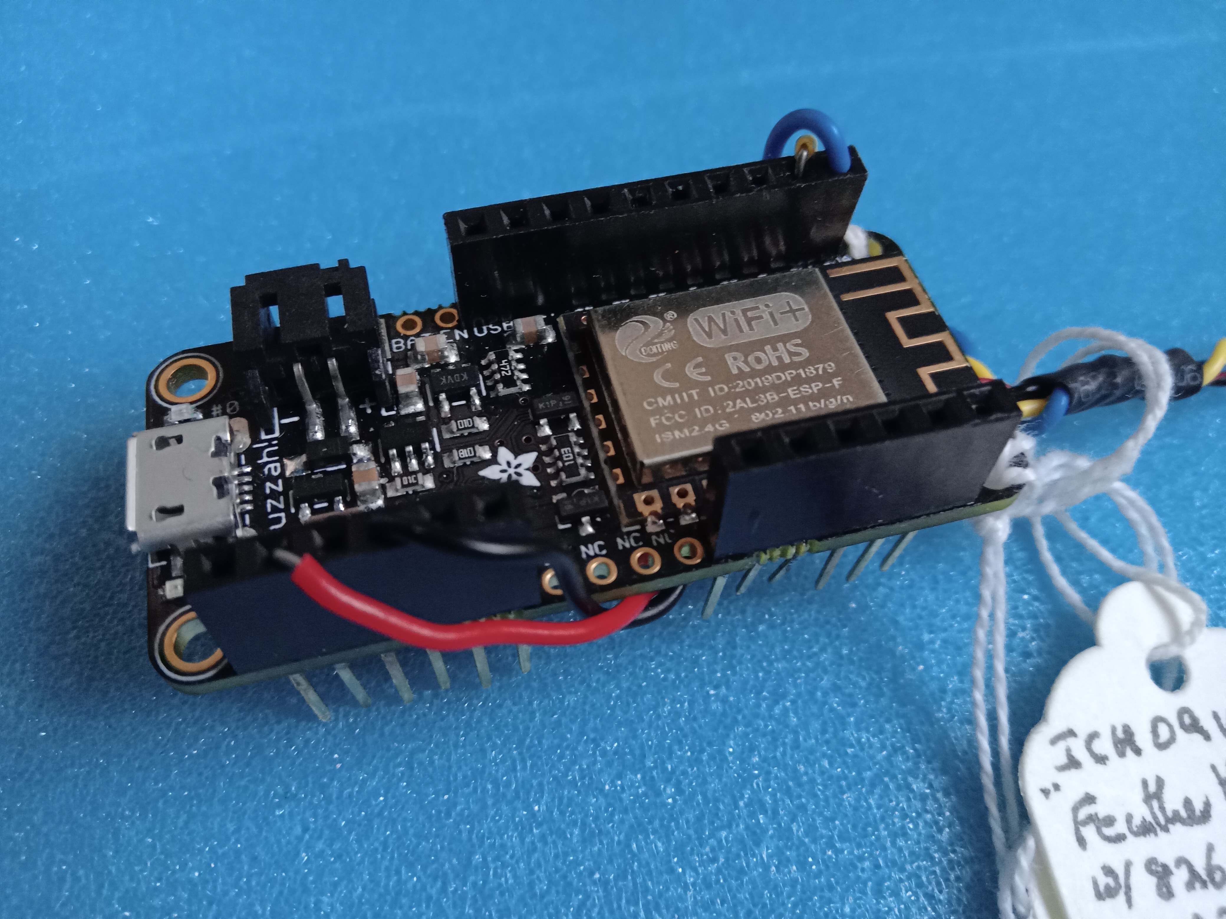
This page is written about my experiences of doing this with a Feather Huzzah 8266. I've done very similar things with a Sparkfun 8266 "Dev Thing". (I'll try to do an appendix someday about the differences needed. They are trivial... but as in all things computery, have to be RIGHT or It Won't Work.)
I'll be using the Adafruit HTU31-D temperature/humidity sensors... their stock number 4832. (The Adafruit device has a nice "frill"... you can set the I2C address of the sensor board to either of two addresses. I wish more boards offered this!) If you are determined to use a different sensor, one without the selectable addresses, the vast majority of this tutorial will still be relevant to you, and, I hope, you will find it easy to do the slight tweaks the code would need.
Leaving options open is part of writing good code.
I've tried to make this "good" code. Not just "something that works".
We'll move on to building the Arduserver!...
I created this version in February 2023. I was using a Windows 10 PC, the version 1.8.13 Arduino IDE, and a recently purchased Feather Huzzah 8266.
Before you invest more of your time in this, I should confess there are some rough edges. The device I describe here isn't perfect. It doesn't watch for or report errors as well as it should. But it DOES WORK quite well... if the sensors are created, the LAN is running smoothly, etc.
I will try to indicate where the rough edges are.
I've had a previous instance of what is described here working happily for over a year. The distance between the sensors on that installation is 60cm. They are connected with a bodged cable I made up. I2C is only "meant" for linking devices on a single PCB! I've had two devices only 50cm apart fail to work across a well made, tidy, commercially-sourced connector! I'll discuss this further in due course... the message for now: You're sensors will have to be close to one another. But you can go a bit beyond the single PCB limit.
---
Still reading? That's the spirit! Thank you.
In addition to the above, there are a number of design goals that are part of all my Arduino projects. Apart from the obvious, I like...
The device should report things like version number, pin allocations, etc whenever it boots. This "internal documentation" goes out on the ordinary serial port. The one used for programming the device. The one to which the serial monitor gives you easy access, if a laptop is connected to the device as it is booting. You don't need the source code. If no laptop is connected, don't worry... the output just "disappears". It doesn't "back up" in the Arduino and cause problems.
---
The code should be easy to read, with well defined-blocks. Any given block should be fairly easy to comprehend in isolation.
I generally dislike global variables. In this project I'm going to let my hair down a bit, use more that I usually do. I am doing this to make the code even easier to read. If I use them carefully, I should avoid the punishments that they sometimes inflict.
First Frill- two "personalities"...
The device will connect to the internet via wifi.
I want it to have a link that you can make or break. The state of the link will determining WHICH of TWO sets of wifi creds it will use. (The two sets of creds (ssid, password, IP address, port) will be stored in the device. (I am building and testing this in one place, for installation at a different place. When it comes time to move it from "the lab" to the place I want to monitor, the necessary wifi creds will change. I want to be able to move the device back and forth easily.)
As hinted at earlier, the report should be easily read by a human... and it should also have something in it that is computer friendly. I will say more on this later.
Second Frill- different sensors...
It should not be hard to set one of these up with different sensors than the ones used in this guide.
Changes to the software will be needed, but if I've written this well, making those changes should not be hard.
---
Third Frill- further sensors...
Both the Feather Huzzah and the Sparkfun Dev Thing would be severely underutilized if all you used it for was the above. But, if that's all you need, $40 doesn't seem like a lot to pay for what it will do.
While building this "limited" device, an attempt will be made to make it easy to add further sensors to the system. For instance, I may put an "is it open or shut?" sensor on a door between the monitored spaces, and add a report of the state of that sensor to what the device provides.
Those are the goals!
What path will we follow to achieve them?
I suggest we START with getting the Arduino "Hello world" Blink! program working in our chosen Arduino. That "should be" simple. Ha! Those fate-tempting words! ("Should be"))
Then we'll make it into a device that puts a simple "Hello." message on the serial monitor. That "should be" simple too!
Then we'll get it to read one HTU31-D, and send the tture and humidity readings from it to the serial monitor.
If the code for that is written well, once we have that working, tweaking the code to send the sensor readings somewhere else should not be hard. (This is an example of how knowing where you are going before you start your journey can be beneficial.)
And again, if reading one sensor is written well, adding the code to read a second should be simple.
Simple! Simple! Simple! Yes! Most of these steps towards our goal ARE small steps... A good development plan makes it possible to reach our goal by small steps.
Once that much is working, you will be shown how to make the device connect to a LAN by wifi and serve up a "Hello LAN" page. (Umm... this step will not be quite as simple as some previous steps!)
Then implement the "choose between two sets of wifi creds" feature.
Then build the page that is "product" that this device was built to deliver, substitute it for our earlier "proof of progress" "Hello LAN" page.
And finally, relatively "trivial", when you know how, we will make our finished and working device visible across the whole internet. (Doing it is simple. Some of the questions you have to consider aren't quite as simple.)
BEFORE you plug in your Feather Huzzah (or any other Arduino), if the last time you used your IDE you were building code for a different Arduino (or clone)...
Use the IDE's "Tools/ Board" to set the IDE to prepare code for the Arduino you are working with. I'll repeat a bit of that... Do it BEFORE you attach the Arduino.
If you are using a new-to-your-system type of Arduino, you may need to use the board manager to download libraries.
All of that is just one of those "always true" things that you need to know if you use more than one sort of Arduino.
---
What did I do first, as I started to code for this project?
I wrote a copy of good 'ol Blink, and ran that in the hardware I intended to use for my project.
Writing that will take an expert 30 seconds. If it takes you longer, the work will teach you things you need, without distractions. It shouldn't take you long to get past this "walk before you run" beginning.
START AS YOU MEAN TO GO ON... and, as you build your Blink, start moving the code towards whatever conventions you like to use in your code.
Here's the "first state" of what will one day be a webserver reporting two temperatures, two humidities, using link-chosen wifi creds. If you actually build it up "alongside me", you will be far better placed to iron out anything that needs a change due to your precise wants and options. You can of course just download my finished version.
(To download, as mentioned earlier: This is the source code. The link takes you to a download. Once you've fetched it (ar787_Feather_2_htu31Ds.zip), unzip it, and put the contents together in a folder with the name name as the .ino file.
=============================
FIRST STATE... 23 Feb 2023, 16:10

/*ar787-2ath312wifi
Vers- see below
Started- 23 Feb 23

*/

/*
Pins used...
  0: For LED_BUILTIN (alias provided by library)
       Drive low to turn on

*/
#define ontime   40
#define offtime 900

void setup() {
pinMode(LED_BUILTIN,OUTPUT);
}//end setup()

void loop() {
digitalWrite(LED_BUILTIN,0);
delay(ontime);
digitalWrite(LED_BUILTIN,1);
delay(offtime);

}
---
The next step, under the development plan, was to get the serial monitor output working. That went reasonably well... but it is one of the places where there are rough edges. I really hate having to put in the crude "delay(200)" to give the system to "wake up" before we start sending data across it. Surely the "while(!Serial) {delay(10;} is supposed to take care of that??
If you always and only get gibberish or less... make sure that the number in your Serial.begin() statement matched the speed your serial monitor is configured to use.
If you sometimes get a bit of gibberish before the messages you've asked the system to send... welcome to the club. (The preliminary gibberish can at least be separated from the Good Stuff if you start the Good Stuff with two blank lines, as I have done in the code presented with this.)
I've tried various baud settings. Nothing seems to help. It is consistent gibberish, just to make it all even more annoying. If you find the solution, do let me know?? (^_^) (Contact details at end. Comments of any sort always welcome. Especially if you point out a place in this where you had to bridge a gap from your own store of knowledge. Spare the next reader that potential problem!)
---
In keeping with my goal of creating easily read code, I've kept setup() and loop() short.
I've "cheated" to do this, of course. Very early in setup(), you can see "SendWelcomeAndDocumentationToSerialMonitor()".
A bunch of stuff because of that one little line... but it is all related to sending a "welcome" message, with documentation of the code and its needs, to the serial monitor. If you to make changes to the message, you go to the subroutine ("SR"). It's "just" bunch of Serial.println() statements, but they are important.
By putting them in the SR, I've left setup() less cluttered. It's not a "cheat" in a bad way... just a sensible tool of writing readable code!
Have I mentioned my other page, dedicated to the Arduino IDE's serial monitor and what it can do for you? Do, please, use it while working on this project. Useful messages are sent there, and, in the early steps of the code's development, that's the only place you'll be able to see what readings the device was able to gather.
The following is our starting point moved on a bit...
/*ar787-feather 2xhtu31d 2xwifi
Vers- see below
Started- 23 Feb 23*/

/*
Pins used...
  0: For LED_BUILTIN (alias provided by library)
       Drive low to turn on*/

#define ontime   40 //for Blink! (Initial stage of prgm devel)
#define offtime 900 //for Blink! (Initial stage of prgm devel)

String sPrgmName="ar787-2at312wifi";//Filename for code
String sInstance="ICH09v";//Code for which Arduino this was compiled for
String sVersID="vers 23 Feb 23-17:00";//Version

//===================================================
void setup() {
pinMode(LED_BUILTIN,OUTPUT);//For Blink test, if nothing else.

//Serial monitor. See https://sheepdogguides.com/arduino/aht1serimoni.htm
//Serial monitor. See https://sheepdogguides.com/arduino/aht1serimoni.htm
Serial.begin(9600);//Get ready to send things to serial monitor.
  while (!Serial) {delay(10);} //Wait for serial port to finish opening
  delay(200);//Don't try to write to the serial monitor too soon. What
    //you try to send may get lost!
    //And you may still get some gibberish in the serial monitor before the
    //message you should get appears. Sigh.
  SendWelcomeAndDocumentationToSerialMonitor();//See code

}//end setup()

//===================================================
void loop() {
  digitalWrite(LED_BUILTIN,0);
  delay(ontime);
  digitalWrite(LED_BUILTIN,1);
  delay(offtime);

}//end loop()

//===================================================
void SendWelcomeAndDocumentationToSerialMonitor() {
Serial.print("Welcome to ");Serial.println(sPrgmName);
Serial.print("Instance: ");Serial.println(sInstance);
Serial.print("Version: "); Serial.println(sVersID);

Serial.println("Hardware: Feather Huzzah 8266");
Serial.println("  D0 left simply driving onboard LED, not used otherwise");
Serial.println("  TX/RX left for just their roles connecting to the IDE,");
Serial.println("     (including the Serial Monitor)");
Serial.println("  D4, D5: Only used for I2C SDA/SCL... Feather defaults");
Serial.println("Software (In addition to basic libraries for the board):");
Serial.println();
Serial.println("-----------");

}//end SendWelcomeAndDocumentationToSerialMonitor
Remember: It is a built-in feature of the code that it is as easy as I could make it to change what sensors are attached to this Arduserver.
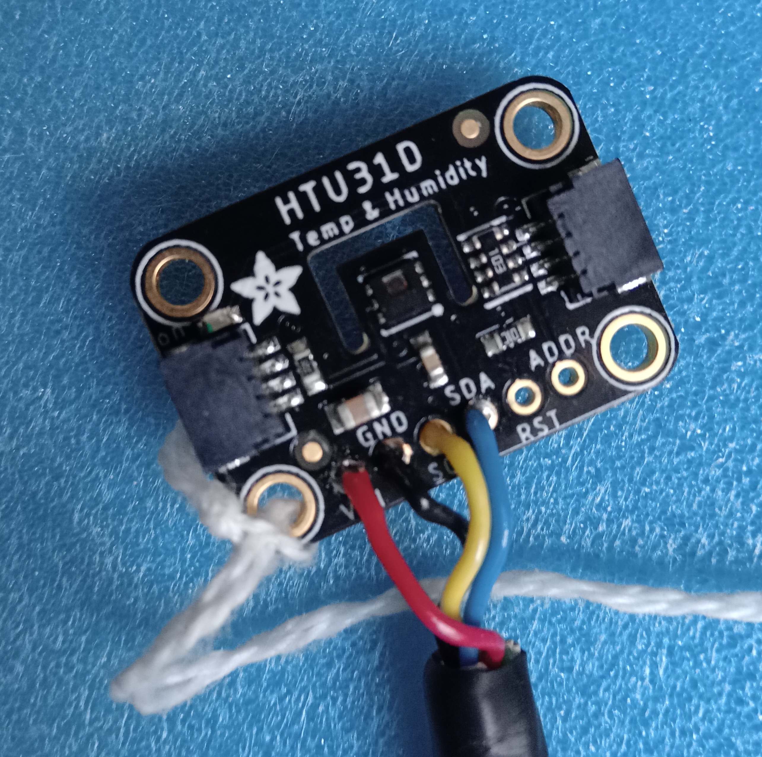
Because they suited what I wanted it for, and for "grist for the mill" here, if nothing else, I used two HTU-31Ds, two Adafruit HTU31D Temperature & Humidity Sensor Breakout Boards, product code 4832. (About $8 each.)
The best help I could find for the device was the Adafruit tutorial about their SHT31-D Temperature & Humidity Sensor Breakout, product code 3832.
NOTA BENE... this is NOT for the HTU31-D, but for the SHT31-D. Remarkably similar!!! BUT NOT THE SAME. You'll have to apply salt.
I'm no expert. I DO know that the AHT31-D's I2C address are 0x40 and 0x41, NOT the 0x44 and 0x45 the SHT31's page speaks of. This is clear from the information in the silkscreen... if you take care to look at it.
There is a wealth of information in the silkscreens on the board... Read it! Use it! (Although the "IC2 addr 0x40" is true only if you haven't made the address link, or pulled the Addr pad high. "Obviously"... but a potential "gotcha", yes? (link and pad discussed below.)
Other than that, for what I wanted to do, the information on the SHT31-D's page seemed as relevant to my HTU31 as it was to the SHT31-D. And they use the same library.
You can connect simply with "...STEMMA QT connectors on either side are compatible with the SparkFun Qwiic I2C connectors. This allows you to make solderless connections between your development board and the SHT31-D or to chain them with a wide range of other sensors and accessories."
Beware: Crossover or straight through? You want straight through, I think. I get confused!
OR you can solder wires to the board(s) in the case of the Adafruit HTU31-D module. Or mix and match. Doesn't matter.
For basic I2C you only have to connect 4 wires.
The four wires carry SCL, SDA, V+ and Gnd. The Adafruit "Learn" page has the wire color conventions listed. Ever the pessimist, I like to combine the colors I'm seeing with where the wire joins the plug. And if, like me, you don't always use the made-up interconnect cables, you'll need the information too.
Another quote from the Adafruit "Learn" page... "[The device] is 3V or 5V compliant." (Have a care over these issues, but I suspect that there won't be a problem using this device.)
The Adafruit pages say that this, "unlike earlier SHT sensors", has a true I2C interface, with two address options.
BE CAREFUL! The humidity sensor is exposed, as of course it must be. Be especially careful while cleaning solder flux residue off of device.
... from Adafruit age about SHT31-D cited below. (I believe these things also apply to the HTU31-D too)...
"RST - Hardware reset input. Has a 10K pull-up on it to make the chip active by default. Connect to ground to do a hardware reset.
"Addr pad: This is the I2C address selection pin. This pin has a 10K pull down resistor to make the default I2C address 0x40. You can tie this pin to Vin to make the address 0x41" NOTE! I have CHANGED the addresses giving for the SHT31-D to the address I know work for the HTU31-D."
An Adafruit page about the sensor breakouts pinout... is very well done... for the SHT31-D... which is NOT the module I am talking about! But there is extensive overlap! (I used the Adafruit HTU31-D, Part 4832, remember.)
There's also a "solder link" on the PCB. Closing that is another way to set the module's I2C address to 0x41.
---
The Adafruit site doesn't always do links from PRODUCT pages to "LEARN" pages... and can be fussy... I think it didn't find the page for the HTU31D OR the SHT31 when I searched on HTU31-D. There was some weakness like that.
First we'll get it to read one HTU-31D...
At this point, our plan to take one small step at a time breaks down a little. Get a cup of coffee. Take a slightly deep breath. Almost NO progress will be visible at the end of the first stage of what follows! But hang in there.
---
To get the crude "read one sensor" result working, we start by...
1====== Just after the...
&hash;define offtime 900 //for Blink! (Initial stage of prgm devel)
... already in the code, add...
#include <Wire.h>//to allow use of I2C
#hash;include "Adafruit_HTU31D.h"//for Adafruit temperature/humidity sensor.
  //Use Tools/ Manage Libraries to install. See the following if
  //  more help needed... https://github.com/adafruit/Adafruit_HTU31D

//The next is part of what you need to read the sensor. Find it mysterious?
//So do I! But, see the comments below it...
Adafruit_HTU31D htu = Adafruit_HTU31D();
//The above is actually a little like the more familiar...
//String sVersID="vers 24 Feb 23-06:00";
//... with which we created a variable: sVersID
//  of a particular TYPE: "String"
//  ... and gave it an initial value: "vers 24 Feb 23-06:00"
//
//"htu" is the "variable" we created.
//The other parts of the line "just work", thanks to things in
// the Adafruit_HTU31D.h library.
//The "initial value" fills bits of htu with various good initial values.
... and...
2======
Just after the...
String sVersID="vers...
... already in the code, add...
byte bErrCode;//Remember: A "byte" variable can only hold 0-255//General purpose
... and ...
3======
At the end of setup() (Just after the...
SendWelcomeAndDocumentationToSerialMonitor();//See code
... already in the code, add...
bErrCode=bSetUpSensors();//(only one, so far)
  Serial.print("SetupSensors reported: ");
  Serial.println(bErrCode);
... and...
4======
At the bottom of the code, add...
byte bSetUpSensors() {
  return 5;
}//end of SetUpSensors
And get it to run... don't worry: I know it doesn't "do" anything yet. And that the "Error code" of "5" doesn't mean anything.
Well, actually it does. If you can get THAT much to run, it means that at least some problems have been ironed out.
You should, of course, be told (in the serial monitor) "SetupSensors reported: 5"!
You will, of course, keep adding appropriate notes to SendWelcomeAndDocumentationToSerialMonitor as you go along, won't you? (^_^)
Now we will add "the guts" to the bSetUpSensors() subroutine. It starts with...
if (!htu.begin(0x40)) {
  Serial.println("Couldn't find sensor on 40!");
  while (1);
  }
(If you run this before reading onward, don't worry of you see strange stuff in the serial monitor!)
I found the "while(true)" that I find weird. Here's what it is all about, for those of you who, like me, hadn't seen that trick in action before. The explanation is in two parts...
At the heart of it, of course, is the
htu.begin(0x40)
0x40 is just a way of writing a number. Whether you write "a dozen", or "12", or "binary 1100"... or even just "xxxxxxxxxxxx" (there are 12 x's)... you are "writing" the same thing. 0x40 is the way we write the number that is the address of an unmodified Adafruit stock number 4832 sensor.
The "htu.begin(0x40)" "comes with" the "variable" (wrong term, but for a beginner, it has some "variable-like" aspects) called htu that we created during setup().
htu.begin() tries to open communications with a chip connected via the I2C channel. The number (0x40, in this case) inside the brackets says WHICH chip. There can be several on one I2C channel... but the are they must each have a different address.
So! This says if... something to do with THAT sensor... (then) do something.
The "Something to do with that sensor", the "htu.begin(0x40)" is a function that sets up communications with the sensor, and returns "true" if all went well, and "false" if not.
Now look again at the code we are unpicking. It says...
if (!htu.begin(0x40)) {....}
Note the exclamation mark. (!)
It says "not". So the code says "if you are NOT able to set up communications, then do what's inside the squiggly brackets."
The "Serial.println("Couldn't find sensor on 40!")" is pretty feeble "error handling"... but at least, if we are looking at the serial monitor, it is a useful bit of information.
(A "Couldn't find sensor" "message" to the on-board LED which could "wink" a message at the user. (Something like that already exists in the source code for the completed project that can download. (See other links in this page.) A pattern of winking on the LED "tells" you that the device is STILL trying to connect to the wifi. Other wink codes should be implemented in due course.)
Then the program goes on to the "while{true}" statement.
"while" makes a loop. The Arduino will go around and around inside the loop until it gets a "false". If all that is in the loop is "true", the Arduino would, other things being equal, just stay there "forever".
Well... and I'm not just being droll here... not after power was removed. Or after the reset button was pressed.
There's another way to reset the device. It is called the "watchdog timer interrupt". It can detect when "nothing has happened" for a while... and "within the meaning of the act", going 'round and 'round a while loop too long is "nothing has happened. Handy, really... if a bit weird, and unsettling. (In a perfect world, we wouldn't even get into an endless loop.
I believe the default is 5 seconds. The watchdog timer can be set for a different wait time. It can be turned off. Searching on "WDT" may be better than using "watchdog".
Note anther way in which our "error handling" is crude: It only looks to see if the sensor can be read at the START of the program's execution. What if, for instance, once the program had finished setup() and had moved on to loop(), the wires to the sensor were cut? We wouldn't be told, as the program stands! In fact we wouldn't even get "bad" readings. The program would just keep giving is the same number as it gave the last time it COULD get a reading. Sigh. But it's a start.
If you do get a timeout, a slew of "stuff" will appear in the serial monitor. Just ignore it!
Shall we move on? Seems a good idea to me!
Right at the start of...
loop()
... insert...
sensors_event_t humidity, temp;
htu.getEvent(&humidity,&temp);
Serial.print("TTure on 0x40: ");
Serial.print(temp.temperature);
Serial.println( C.");
delay(500);
("temp" for "temperature", as you probably guessed... but wouldn't tture be a better shorthand for that? But we can't change that. Not here.)
Run the program. Watch the serial monitor! You should be seeing temperature readings! Put your finger on the BACK of the sensor, and you should see the temperature rise immediately! Whew! Took enough work to get that far!!!
I wouldn't blow warm breath too enthusiastically at it... you might upset the humidity sensor with your very moist breath. Once you've got the device reporting the humidity, you will see that even a modest puff of breath from 15cm away is enough to cause a spike in the humidity readings. A modest puff will tell "it's working"! (Once it is!)
--
We should just touch on the latest weirdnesses before moving on...
"sensors_event_t humidity, temp"??? Where did this come from? And "humidity" and "temp"? I can't comment intelligently. I Just Use It. With my thanks to whatever website had the sample program I've based that part of all this upon. Maybe it was in the github archive, or maybe it was the good article at...
"humidity" and "temp" are again a bit like variables, but we don't need to do anything about setting these up. (That's part of the reason we can't change the name on "temp".)
(That's worth reading anyway, to supplement this, to check that what you read there doesn't alert you to things you need to know that you didn't learn here.)
"htu.getEvent(&humidity,&temp)"??? Again, I can't say much about this. Note it starts "htu", and remember that we "set up" a "variable" called "htu" earlier in our code. This will be important later. As an idle, incomplete bit of information for you: The question marks say "access what's stored in "humidity" and "temp"... but access them differently from how we access them elsewhere in the other code that we are Just Using.
... and now we WILL Move On... (^_^)
----
All that was a bit of a pain, I know.
The next bit is much nicer! Well, it will be for you. I got sucked into about 3 hours of running is circles over something subtle to get "here" for you! But I want this device for my own purposes, so it's okay.
Time to add a second sensor! (We'll come back to the humidity reading later. Trivial to add.)
=== Changing the software to make it read another sensor is pretty simple. On the software side, as you probably guessed, adding a second sensor is mostly just a matter of "doubling up" some things. We'll come back to that in a moment.
Adding the hardware isn't hard if you have the Adafruit stock number 4832 HTU31-D, and the right cable. You just plug one end into one of your HTUs and the other into the other! It doesn't matter which of the sockets you use.
But your cable must not be too "long". And "too long" is not very long at all. I've had a bodged, self-made cable connecting two sensors for more than a year, and it has all "just worked". Today, when I was doing this for you, I had a nice, commercially made, cable... only 50cm long... and it wouldn't do. When I ran the program I got the "cannot find sensor on 41" message.
Here's a Gotcha to watch out for: Remember: The test that leads to that message is only executed as the program is starting up. (Yes- I probably SHOULD make it occur more often. Hey!... there are only so many hours in the day.)
And another: If the sensor dies, or becomes disconnected, after the program has got into the loop() routine, you won't know it! Apart from the fact that the "readings" "from" the lost sensor will just keep coming back with the same numbers at it reported before becoming un-reachable.
If you need to make up a cable, or if you are connection the sensors via the pads on the PCB, don't over think it. You need a "straight through" cable.
** xxDIAGRAM GOES HERE... later. Sorry. **
Call one side of the plug on the cable the "holes side"... if you look closely, you will find that the tiny holes are much closer to one side than the other.
Hold the cable with the two plugs pointing away from you. "Holes side" up for both of them. Held like that the left-hand-most wire will be for the connection between the "ground" or "zero volts" of the two devices. The next to the right will be for the voltage that makes them work. The next will be for SDA signal, and the right-hand-most wire will be carrying they SCL signal. "Officially", although of course it won't affect the electronics, the wires, from left to right, "should" be: black, red, blue, yellow.
Now... don't be alarmed if you notice the following:
If you stretch the cable out "flat" onto a straight line, with no twists in it, you should find that one of the plugs is "holes side" up, and the other down. This is how it is meant to be. If you can do the mental gymnastics to "see" that this is true, you have my envy. I struggled and struggled, because if you use a different cable, it might not be good for the electronics. Thankfully, I had my "working" two HTU-31s device to "consult" about what is "right".
I could talk about the cables for a long time. But I want to get on to other things. You can do this! If things aren't working, try a shorter cable. Swap the sensors around. (I found that either of mine would work as the one near the Arduino. The one that wouldn't work was always the distant one. I found that it didn't matter which socket on the sensor I used. It didn't matter if I used wires soldered to the pads.)
===
Changes to software to add a second sensor...
Just be careful sometimes very little differences between what you have, and what you should h have can cost hours of head-scratching. It's still "Serial.print" to make things go to the serial port, be they readings from the sensor with I2C address 0x40 or from the one with address 0x41. And others DO need something to distinguish which sensor they relate to.
But be careful not to assume which DO change, and which don't will be "obvious".
You need to "double up" in 5 places. Below, I have shown you the bit we already have for reading the first sensor, and the bit we need to read a second...
1=== Adafruit_HTU31D htu = Adafruit_HTU31D(); Adafruit_HTU31D htu41 = Adafruit_HTU31D();
2=== if (!htu41.begin(0x41)) { Serial.println("Couldn't find sensor on 41!"); while (1); }
3=== sensors_event_t humidity, temp; sensors_event_t humidity41, temp41;
4=== htu.getEvent(&humidity, &temp);// populate temp and humidity objects with fresh data
htu41.getEvent(&humidity41, &temp41);// populate temp and humidity objects with fresh data
Make those changes, and then get the code to run again. (Fix typos, etc.) It yet REPORT more than it did before: The temperature seen by the first sensor. But it should run.
========
Once you've got the above working, you'll add to what appears on the serial monitor...
While we're at it, we'll get the humidity readings displayed too.
As you can probably work out for yourself, the temperatures and humidities are available in...
Temperature Humidity
Sensor at I2C 0x40: temp.tempeature humidity.relative_humidity Sensor at I2C 0x41: temp41.tempeature humidity41.relative_humidity
I thought the serial monitor display would look nice like this...
Tture on 40, then 41: 23.49 C, 23.81 C.  Humidity on 40, then 41: 41.30 % RH, 39.74 % RH
Tture on 40, then 41: 23.45 C, 23.77 C.  Humidity on 40, then 41: 41.13 % RH, 39.68 % RH
Tture on 40, then 41: 23.45 C, 23.75 C.  Humidity on 40, then 41: 40.98 % RH, 39.61 % RH
Tture on 40, then 41: 23.35 C, 23.85 C.  Humidity on 40, then 41: 40.87 % RH, 39.58 % RH
Tture on 40, then 41: 23.41 C, 23.85 C.  Humidity on 40, then 41: 40.79 % RH, 39.58 % RH
... therefor, the code for printing out the readings obtained looks like this...
      Serial.print("Tture on 40, then 41: ");
      Serial.print(temp.temperature);
      Serial.print(" C, ");
      Serial.print(temp41.temperature);
      Serial.print(" C.  ");

      Serial.print("Humidity on 40, then 41: ");
      Serial.print(humidity.relative_humidity);
      Serial.print(" \% RH, ");
      Serial.print(humidity41.relative_humidity);
      Serial.println(" \% RH");
That "should work", if you got past the "if (!htu41.begin(0x41))..."
For testing the humidity sensor, you can "breath", gently, towards the sensors. They are remarkably sensitive. Treat them gently, and try to avoid really high humidities. (The sensors can handle them but other issues begin to arise.)
I hope you were delighted, that the line after line of readings began appearing without too much hassle? (If there WAS hassle, please tell me where... so I can modify this, save the next person. (Contact details at bottom.)
Remember what I said about getting the I2C to work, if you haven't reached the reward stage yet. Try a shorter cable. At least down to 10cm, though I would hope it doesn't need to be that shore... and indeed, as I've said, I've got it working over (slightly) longer distances.
=====
What we really OUGHT to do now is to tidy what's in setup() and loop(). We could slim them down. move "stuff" out into subroutines, the way we used SendWelcomeAndDocumentationToSerialMonitor earlier.
But where's the fun in that? (The "fun" is that the program is easier to read, so we will spot flaws more easily, and get a fully working, meets whole spec, device SOONER.
But I Don't Want To do that just now.
Copy of code, as taken this far...
/*ar787-feather 2xhtu31d 2xwifi
Vers- see below
Started- 23 Feb 23

*/

/*
Pins used... See notes in
  SendWelcomeAndDocumentationToSerialMonitor()

*/
#define ontime   40 //for Blink! (Initial stage of prgm devel)
#define offtime 900 //for Blink! (Initial stage of prgm devel)
#include <Wire.h>//to allow use of I2C
#include "Adafruit_HTU31D.h"//for Adafruit temperature/humidity sensor.
//Use Tools/ Manage Libraries to install. See the following if
  //  you want help with that... https://github.com/adafruit/Adafruit_HTU31D

//The next is part of what you need to read the sensor. Find it mysterious?
//So do I! But, see the comments below it...
Adafruit_HTU31D htu   = Adafruit_HTU31D();
Adafruit_HTU31D htu41 = Adafruit_HTU31D();
//The above are actually a little like the more familiar...
//String sVersID="vers 24 Feb 23-07:00";
//... with which we created a variable: sVersID
//  of a particular TYPE: "String"
//  ... and gave it an initial value: "vers 24 Feb 23-06:00"
//
//"htu" is the "variable" we created.
//The other parts of the line "just work", thanks to things in
// the Adafruit_HTU31D.h library.
//The "initial value" fills bits of htu with various good initial values.

String sPrgmName="ar787-2at312wifi";//Filename for code
String sInstance="ICH09v";//Code for which Arduino this was compiled for
String sVersID="vers 24 Feb 23-17:05";//Version

byte bErrCode;//Remember: A "byte" variable can only hold 0-255//General purpose


//===================================================
void setup() {
pinMode(LED_BUILTIN,OUTPUT);//For Blink test, if nothing else.

Serial.begin(9600);//Get ready to send things to serial monitor.
//"Serial monitor"?. See https://sheepdogguides.com/arduino/aht1serimoni.htm
while (!Serial) {delay(10);} //Wait for serial port to finish opening
delay(200);
//Don't try to write to the serial monitor too soon. What
    //you try to send may get lost!
    //And you may still get some gibberish in the serial monitor before the
    //message you should get appears. Sigh.
  SendWelcomeAndDocumentationToSerialMonitor();//See code

  if (!htu.begin(0x40)) {
    Serial.println("Couldn't find sensor on 40!");
    while (true);//"true", not "TRUE"
    }

  if (!htu41.begin(0x41)) {
    Serial.println("Couldn't find sensor on 41!");
    while (true);//"true", not "TRUE"
    }

bErrCode=bSetUpSensors();//(only one, so far)
  Serial.print("SetupSensors reported: ");
  Serial.println(bErrCode);
}//end setup()

void loop() {
  sensors_event_t humidity,   temp;
  sensors_event_t humidity41, temp41;

  htu.getEvent(&humidity,&temp);//You can't insert space in this line
  htu41.getEvent(&humidity41,&temp41);//   to make it "line up" with this.

  Serial.print("Tture on 40, then 41: ");
   Serial.print(temp.temperature);
   Serial.print(" C, ");
   Serial.print(temp41.temperature);
   Serial.print(" C.  ");

   Serial.print("Humidity on 40, then 41: ");
   Serial.print(humidity.relative_humidity);
   Serial.print(" \% RH, ");
   Serial.print(humidity41.relative_humidity);
   Serial.println(" \% RH");

  digitalWrite(LED_BUILTIN,0);
  delay(ontime);
  digitalWrite(LED_BUILTIN,1);
  delay(offtime);
}//end loop()

//=======================================================
//*******************************************************
//The remaining blocks in this code are listed below in
//strict alphabetical order, using every character found
//on the first line of the block.
//-------------------------------


//=======================================================
byte bSetUpSensors() {
  return 5;
}//end of SetUpSensors

//=======================================================
void SendWelcomeAndDocumentationToSerialMonitor() {
Serial.println();
Serial.println();
Serial.print("Welcome to ");Serial.println(sPrgmName);
Serial.print("Instance: ");Serial.println(sInstance);
Serial.print("Version: "); Serial.println(sVersID);

Serial.println("Hardware: Feather Huzzah 8266");
Serial.println("  D0 used simply to drive the onboard LED; no other use");
Serial.println("  TX/RX left for just their roles connecting to the IDE,");
Serial.println("     including communication with the Serial Monitor.");
Serial.println("  D4, D5: Only used for I2C SDA/SCL... Feather defaults");
Serial.println();
Serial.println("Software (In addition to basic libraries for the board):");
Serial.println("  Adafruit_HTU31D.h: For the Adafruit temperature/humidity");
Serial.println("     sensor. Use Tools/ Manage Libraries to install. See ");
Serial.println("     https://github.com/adafruit/Adafruit_HTU31D");
Serial.println("     if more help needed.");
Serial.println("-----------");
}//end SendWelcomeAndDocumentationToSerialMonitor
=========================
Starting to make the wifi part happen...
"Making the wifi happen" is a huge subject. I don't know as much about it as I do about other parts of this. Read the following with some skepticism. Keep your brain questioning. All I can say is that the code DOES work!
=====
Any device on a LAN... and when you "connect via wifi", you are putting a device on a LAN!... has a numeric "address". (By the way: It's a bit like the I2C address we met earlier... but not in ways that are likely to help you here. Sorry. Just saying.)
The device's address, as far as the LAN is concerned, is probably something like 192.168.000.042.
That's a way of writing a Very Big Number. We never write the VBN "normally". Under IPv4, which is what most hobbyists, schools, etc, use, the number, written the way we do it, always consists of four numbers separated by "."s.
Very often, the first two numbers are 192 and 168, as in the example above.
All of the numbers, always, are in the range 0-255, inclusive.
You don't have to write out any leading zeros. The number I gave above...
192.168.000.042 can be written... 192.168.0.42 without it mattering at all. This is the "internet protocol address" for the device. Often called it's "IP address". This is it's IP address for the LAN.
If you go further, and fix things so that people out there in internet land can read your device, they won't talk to it via the number we have been discussing. They will "go through" a part of your router that "faces outward". It has a number that is different to the number (IP address) by which it is "known" by the devices on the LAN.
Hang in there. We're nearly done!
I like to call the router's "outward looking" IP address a "WIPA", for "Wide area network IP Address", and the IP addresses used LOCALLY, "inside" the LAN, "LIPAs".
====
Moving on. Even though you may have questions. Get the following straight as a starting point, and it may make it easy for you to, eventually, become clear on other aspects of all of this.
====
On many LANs, a device, probably the router, chooses LIPAs for things as they are plugged into the LAN. And this works perfectly well... for many wants.
However, for something like what we are doing, I prefer a different approach. I'm afraid you're going to have to dig around a bit if some of the following is unfamiliar ground, but I will at least have given you the terms!
I tell the DHCP controller (that's what dishes out the LIPAs) to set aside some of the numbers usually available to IT, and let ME have the gift of those LIPAs.
In a simple LAN, everything's LIPA will have the same first three parts their LIPA... quite often 192.168.0. It is only the last number that varies between the devices on the LAN. But that still leaves more than 100 available.
Let's say that you told your DHCP controller to NOT use LIPAs 192.168.0.50 to 192.168.0.180.
Fine. That would make them available to YOU! And you can, as I will in the software that follows, "tell" a device "connect to the LAN via <THIS> LIPA... say 192.168.0.55, for example. This is called using a "static" (unchanging) IP address.
Complicated in some ways, and not "the answer" for everyone, in every situation. But for what we're doing, and for the sort of person I imagine is reading this it is a Nice SIMPLE Answer! If you keep good records of what LIPA you've "given" to which device. Well... "simple" compared to the alternatives!
You DO need to be careful NOT to connect two things to a LAN that both have the same static LIPA. I don't think it will do anything any harm, but Things Won't Work.
You may feel that using a static LIPA is not for you. Fine. The code would need only a small tweak. (Generally speaking, tutorials on the web assume that you will be using the alternative, DHCP. When I adapted one of those to switch it to using the static LIPA, the tweak was small.)
Using a static IP address has its place. I hope this tutorial will be found by someone wanting to take that approach. When I was learning what I needed to, I couldn't find much help! N.B. I'm talking about a static IP for the device's place on your LAN. A static IP for "where" your router connects to the internet is possible, but you don't need to spend the hundreds of dollars per month it would cost to get one!
If you DO decide to go with DHCP, you'll have a problem when it comes to connecting your device to the outside world, to the internet generally. That can be overcome if your router can assign a fixed LIPA based on the device's MAC. There is a way to give your Arduino whatever MAC you want it to have. I just find static LIPAs easier. A solution with fewer Things To Go Wrong.
We'll come back to this whole LIPA thing when we get going on the code for our device. But now you know enough of THAT theory.
===
A bit like LIPAs are "ports". Another number.
I'll try not to go too far into what ports are, but we need to cover them a bit... in a moment.
But first...
===
What can you attach to a LAN???
Lots of things! As you know. But think about it for a moment. You can attach a PC, and Do Things. You can attach a printer, and send jobs to it across the LAN. You could... really!... have "an FTP server", or a "MySQL database server". You may HAVE a "File server"... a bit like an extra hard disk, not inside your computer, but almost like the one inside your computer, just attached across the LAN.
How cool!
But we're going to make a WEB server. Our little device, the one that can already read two HTU31's will ALSO be a "web server".
What is a web server?
Any time you "go to Google" to get information, you are connecting to a "web server".
If you are just using a simple internet browser (Firefox, Chrome, etc), and doing simple things, you are going to a webserver somewhere.
Your web browser puts together a request. It might be a request for a weather report for your area. It goes across your LAN, through your router, and off across the internet to a web server.
The web server has, if you like, a "reception desk".
"Someone" there looks at the request you've sent. The server prepares some "stuff", in a very particular code... and sends that back to you. (Your request arrives with a "return address" on it.)
Your browser knows what to do with "the code", and fills your screen with a human-friendly version of what was in the code.
Brilliant!
And your little Arduino sensor reader is ALSO going to do all the stuff that the webserver I spoke of a moment ago does!
At this point in the evolution of this page and the system it described, I became too wrapped up in the coding, and neglected contemporaneous records of What I Did Next. Sorry. Some of what I did you will have to figure out by yourself from reading the source code. As I've said... it DOES WORK, for me. I hope you can get it working FOR YOU easily.
Big thanks to alselectro's page about the ESP8266 library.
The struct word lets you create records (the term used in a narrow sense. I'd used them in other languages. Not strictly "necessary", but nice when you know how.
This (ar787, 2 March '23) was the first time I'd used them in Arduino work. My thanks to this discussion at forum.arduino.cc for helping me get started with them in Arduinos.
We are going to read two sensors. We could have a slew of ordinary variables to deal with this. In a perfect world, if I were going that route, I'd have something like...
float fSensor0Tture, fSensor0Hum, fSensor1Tture, fSensor1Hum
(Arrays are also an option, of course.)
With struct and record I can set something up called "SensorReadings", with "parts".
SensorReadings.Tture0
SensorReadings.Hum0
SensorReadings.Tture1
SensorReadings.Hum1
That's what I did. And it was foolish.
I should have created two instances of my new... "class"? I'm not sure of the right name. They would be...
SensorReadings0 and
SensorReadings1
EACH would have it's own "Tture" and "Hum" "places" to store a number
ANYWAY... bottom line, for now, I set things up WRONG... but it still left me with places like variables where I could put things. By the time you read this, I may have split things up more intelligently.
Sorry that's a bit sketchy! Study the code, and remember that, end of the day, the "stuff" associated with the "struct" declared near the top of the code is essentially variables where things can be stored.
Eventually, I may also use a similar mechanism in connection with creating the selectable wifi creds feature.
Mini tutorial regarding struct and record...
Put the following near the top of your code, outside of any SR declaration...
struct TMyRecord
{
    int  iFirst;
    byte bFishcakes;
};

typedef struct TMyRecord MyRecord0, MyRecord1;
Once you've done that, you have created, declared, whatever, FIVE things...
Obviously, I hope, given what I wrote earlier, you've created four variables. Or if that's not the right term, you've created four things that work like a variable...
MyRecord0.iFirst
  MyRecord0.bFishcakes
  MyRecord1.iFirst
  ... and...
  MyRecord1.bFishcakes
The other thing you created was TMyRecord. Again, I'm not sure of the right term. Due to my background, I call such things "Types", hence the T prefix on the name I gave the... thing... I created. The thing called "TMyRecord".
Look at how it is used in the example. It is almost like a user defined data type. And it creates RECORDS, (using the term as database people would use it), hence I would usually call MyRecord0 and MyRecord1 "udrMyRecord0" and "udrMyRecord1". That's just a logical extension of the habit I have of putting a "i" at the front of all my integer-type variables, "b" in front of byte-type variables. (That system is called Hungarian notation, and I commend it to you!)
This project uses many standard libraries... in the standard way!
For instance, early in the code we see
#include <Wire.h>
It ALSO uses a little library I wrote. Early in the code, we see...
#include "Tkb1stLib.h";
(No, I haven't made a mistake... < and > around one of the library's name, quotes around the other's. We'll come back to this.
When you load the .ino file that is on offer, besides the usual tab, there are tabs for Tkb1stLib.h and Tkb1stLib.cpp
Some of the subroutines used by ar787 are defined in those files.
Why #include <Wire.h> and #include "Tkb1stLib.h";? You use the former for any library that is installed as an integral part of the IDE, and the latter for libraries that are provided as part of the .ino file. If you look at the folder the .ino file is in, you will see files of those names.
Most of what I know about user created libraries comes from the excellent... https://roboticsbackend.com/arduino-create-library/
Forgive me stopping rather abruptly here. I want to get back to the final stages of writing the code! That's fun! Doing web pages is Good For Me. Right up there with peas and broccoli. If a few people would write once in a while, say "thanks- that helped", or even "What did you mean when you said...", maybe I'd be more enthusiastic. Hint. Hint. Fish for a compliment? Moi?
Seriously: PLEASE mention this page in forums, etc, if you think it answers a question someone was asking. I accept that building a readership, and keeping it, can't happen overnight. And I do understand this isn't a glossy as some things that are popular. But I wrote it because it contains things that I had trouble finding while I was building this. PLEASE spread the word, if you think there is ANY value in this. And if you don't, why have you read this far??
I have, by the way, done the feature whereby a user can "re-program" the device to use an alternative set of wifi creds simply by inserting or removing a link between two of the Arduino's pins.
Please get in touch if you discover flaws in this page. Please mention the page's URL. (wywtk.com/fw/ardusftw/ar787/ar787_arduserver.htm).
If you found this of interest, please mention in forums, give it a Facebook "like", Google "Plus", or whatever. If you want more of this stuff, help!? There's not much point in me writing these things, if no one feels they are of any use.
|
Unlike the clever Google search engine, this one merely looks for the words you type, so....
* Spell them properly.
* Don't bother with "How do I get rich?" That will merely return pages with "how", "do", "I"....
Please also note that I have three other sites, and that this search will not include them. They have their own search buttons.
Page has been tested for compliance with INDUSTRY (not MS-only) standards, using the free, publicly accessible validator at validator.w3.org. It passes in some important ways, but still needs work to fully meet HTML 5 expectations. (If your browser hides your history, you may have to put the page's URL into the validator by hand. Check what page the validator looked at before becoming alarmed by a "not found" or "wrong doctype".)
AND passes...

....... P a g e . . . E n d s .....